Table of Contents
This small technical document describes Joshi. Joshi is a program that tries to recognize shapes on images, or so called bitmaps, by converting the images to polygons and then compare these with ones that were already stored and identified. Joshi has a focus on recognizing characters also known as OCR. Currently Joshi is able to recognize single characters as long as they do not exist of multiple parts like the characters 'i' and 'j'. Neither is Joshi capable of cutting shapes so that characters that are printed close to eachother are not treated as single characters and Joshi can not recognize them. Altough an algorithm is implemented to cut polygons in half it stays a problem where to cut a polygon in two or more parts.
Joshi can recognize single characters. So then why can't it produce simple ASCII output or a nice OpenDocument file? This is simply because a good algorithm for recognizing lines and words is not implemented yet. This problem appears just as hard as detecting single characters. I.e. can you tell on a random image which character is completly in the top left corner. If a scanned image is a bit rotated then can you still tell which character is in the top left corner? Combined with this problem is recognizing characters consisting of multiple parts and cutting characters so they are correctly recognized.
As mentioned above Joshi is build to recognize shapes and therefor it could recognize other shapes then characters as well. Ofcourse there are some limmitations. Joshi currently runs in black and white only. You can hand over any colored images but it will internally convert it to black and white only. Overlapping shapes are currently not supported. Rotations are not supported only small rotations in 2D. Any other transformations to shapes are not supported. Furthermore Joshi does not care what shapes it needs to recognize, it can recognize Chinese, Japanese or any other type of characters. But it could also recognize chairs, tables and/or lamps.
Joshi is meant to run as a service. For feeding the shapes Library of Joshi the UI is practical, but once the library is filled it is is not necessary to run the UI anymore. Therefor Joshi is split into two parts namely the main part and the UI part. The main part is able to run without the UI part. Currently this is not configurable in the properties file or with the arguments. Instead the JoshiUI is to be left out of the Java classpath.
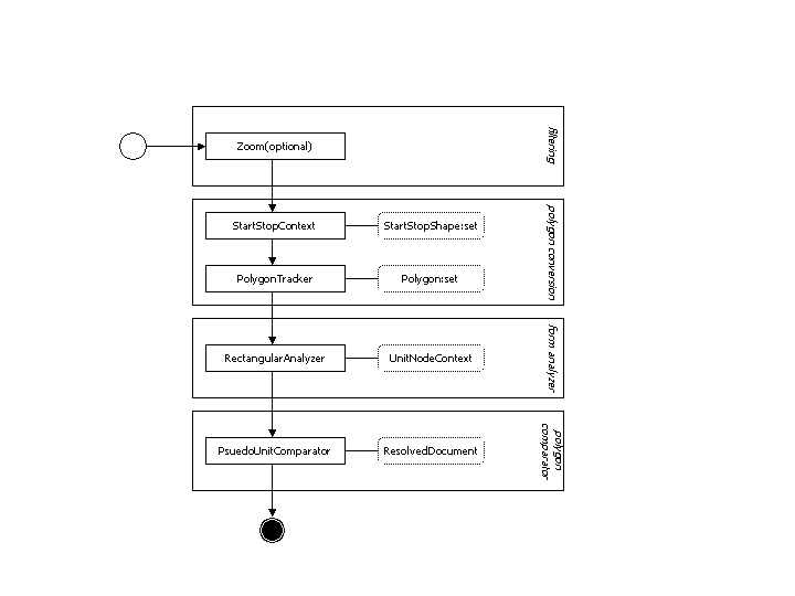
The main part is found in the subdirectory JoshiMain. When compiled and build using the ANT script this will result in a JoshiMain_xxx.jar file. The main part is, as mentioned in the introduction of this chapter, responsible for the actual shape recognition. This process is split into multiple steps as shown in the figure below.
This chapter describes what Joshi defines as a Polygon, how it converts images into polygons and how you can use these methods. You should be aware that the Polygon class used in Joshi is different from the one used by the java.awt package. A polygon in Joshi is defined as a single shape with one outerline and zero or more innerlines (or holes). As described at http://en.wikipedia.org/wiki/Polygon Joshi assumes all polygons to be concave simple polygons. Wikipedia states that a polygon is a closed planar path, which differs with the definition of a polygon used in Joshi. In Joshi a Polygon is build up of one ore more closed planar paths whereas the first is the outer path and the next are inner paths. Instead a Polyline is defined as a single planar path and therefor is in compliance with the definition of the polygon in Wikipedia.
Joshi uses an image to polygon converter which does not support color nor does it support grey scales. Therefor images have to be filtered to black and white. White is assumed to be the background color whereas black is assumed to be the foreground color. This filter is just one of multiple steps before a polygon is parsed from the image. Hereunder is the list of steps that Joshi takes to create the polygons.
Filter image to black and white.
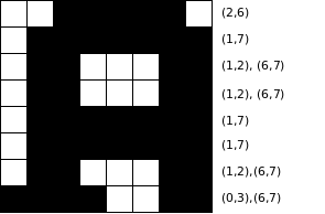
Create an ordered list of start-stop combinations for each scanline of the image. Where the order is from the left to the right and a scanline is defined as a single horizontal line.
Combine all start-stop combinations that overlap eachother and create StartStopShapes from them.
Run all StartStopShapes through the PolygonTracker which creates the polygons.
The StartStopContext is responsible for feeding the PolygonTracker. It does so by creating StartStopShapes that allow the PolygonTracker to retrieve single circulair paths consisting of points. The StartStopContext starts by scanning each line from the left to the rights searching for variations from white to black and from black to white. Since white is assumed to be the background color it starts with white. Every change from white to black is considered as a start value which is always followed by a change from black to white (after the most right point the background color is expected) which is considered as a stop value. These two values (start and stop) are stored in a StartStop instance which is the stored in the StartStopLine created for the specific line. These StartStopLines are storead in an array of which the length is exactly the height of the provided RGBArea (read image). If all lines of the area are scanned and the StartStopLines are filled with the resulting data then theoratically the image could be recreated using these array of StartStopLines.
Having these StartStopLines filled with StartStop values we can start to combine them. StartStopValues are combined when they are, either directly or indirectly, connected with eachother. To better understand what is meant by this you should imagine opening your favorite bitmap oriented paint program draw some random stuff on it with black, select the fill option and select the color green. Finaly point the mouse on a black dot and start the fill. All dots that now appear green would be combined to a single StartStopShape. Though I could have build a fill routine this is not how Joshi approaches this problem. Instead it searches for StartStop values that overlap eachother. Two StartStop values overlap if the lines they are on directly follow eachother and if one of the start values lays in between the start and stop value of the other. For each StartStop value it is valid that multiple StartStop values can overlap it on both the preceding line and the succeeding line. Therefor a stack is used to push these overlapping StartStop values that are found. Once a StartStop value is analyzed for overlapping by other StartStop values it is being marked as done and put in the pending StartStopShape. StartStop values being marked will never be pushed on the stack again. If the Stack becomes empty the current pending StartStopShape is finished and the algorithm searches the array of StartStopLines for another unmarked StartStop value which it pushes on the stack and repeats the above procedure. In the end all StartStop values will be marked and a list of StartStopShapes created.
The PolygonTracker provides the method called track that converts a StartStopShape into a Polygon. The PolygonTracker is responsible for converting start-stop-shapes into polygons. The convertions runs in three stages.
Create a circulair list of all outer points of the StartStopShape using the PathIterator provided by the StartStopShape class.
Reduce the number of points in the list by connecting two points in the list and calculating the distortion for the points in between
Creating a PolyLine instance of the list of 'reduced' points and add it to the Polygon
The PathIterator provided by the StartStopShape class is a double iterator. The outer iterator iterates over the multiple ciruclair point-lists a StartStopShape can be made up off. I.e. the character 'S' has a single circulair point-list, the character 'e' has two circulair point-lists and the character 'B' has three point-lists. The inner iterator iterates over the points in the StartStopShape that when enlisted result in a single circulair point-list. Thus the StartStopShape itself does not maintain this list, instead the PathIterator calculates the order in realtime using an specific algorithm to extract this info from the start-stop infos stored in the StartStopShape. In order to seperate the lists, those that are provided by the outer iterator, the PathIterator markes every point it passed. The outer iterator will search, from the top-left to the right-bottom, for the first unmarked point in the StartStopShape which will be the first point of the list that follows. If no more unmarked points are left then all work is done for the PathIterator and no more lists will follow. Note that the first unmarked point of a StartStopShape, which is completely at the top-left, is always a point that is on the outer polyline of the polygon. All that follow are inner polylines (or you could say holes) of the polygon.
A Circulair point list provided by the PathIterator could directly be used to create a polyline. This would create a polyline that has lots of points, lots of lines to be drawn and needs a lot more calculations in a later stadium where the polygons are being compared. To improve the quality of the polyline Joshi reduces the number of points by detecting which points lay approximatly on the same line. The pseudo code for reducing the number of points in the point list is listed below
Procedure 2.1. Pseudo of point reduction
create and initialize first-offset and last-offset.
repeat while not all points have been 'passed'
repeat as long as distortion of the line between the points index by the first-offset and last-offset is within limmits.
Increase last-offset
Calculate the distortion of the line defined by the points indexed by the first-offset and the last-offset.
Calculate the index of the point that is the farrest of the line defined by the points indexed by the first-offset and the last-offset. This index is stored as the next-offset.
Store the point indexed by the next-offset in the result list
copy next-offset to first-offset
Distortion is calculated by taking the distance of each point to the line and accumalating them into either a left-total or a right-total. The absolute difference between the left-total and the right total is then cosindered to be the distortion.
Below is a small example how to use the PolygonTracker on a BufferedImage.
   // create a BufferedImage
   BufferedImage image = new BufferedImage(100, 100, BufferedImage.TYPE_INT_RGB);

   // draw a triangle on it
   Graphics gfx = image.getGraphics();
   gfx.setColor(Color.WHITE);
   gfx.fillRect(0,0, image.getWidth(), image.getHeight());
   gfx.setColor(Color.BLACK);
   int xcoords[] = { 0, 100, 0 };
   int ycoords[] = { 0, 50, 100 };
   gfx.drawPolygon(xcoords, ycoords, 3);

   // create a StartStopContext from the image
   BufferedImageArea area = new BufferedImageArea(image);
   StartStopContext startStopContext = new StartStopContext(area, 1f);

   // get the first StartStopShape from the context
   StartStopShape shape = startStopContext.iterator().next();

   // create a PolygonTracker instance and run the shape trough it.
   PolygonTracker polygonTracker = new PolygonTracker();
   Polygon polygon = polygonTracker.track(shape, 1f, shape.getLocation());
A Unit is the holder for a StartStopShape and with that connected the Polygon. The PolygonTracker which is described in the previous chapter holds no context it only provides the logic to convert StartStopShapes to polygons. Instead of the PolygonTracker holding the context the UnitContext does. So the UnitContext could be interperted as a polygon-context. Since the Unit does not only hold the polygon but the StartStopShape as well, and since the polygon is just a representation of the StartStopShape, the term PolygonHolder would have been inappropriate.
Pseudo units are a combination of units and parts of units. Whereas the unit represents just a single shape the pseudo unit represents complex combination of shapes. The unit is always a copy or an representation of the image a pseudo unit must not be that. A pseudo unit consists of one or more pseudo parts. Each pseudo part holds a reference to at lease one unit. A pseudo unit can be interpreted as a programm describing how a PolygonSet is created. Each PseudoPart is a single programm-command which appends zero, one or more polygons to a PolygonSet. A PolygonSet is a class holding a collection of polygons.
The definition base is a repository for 'learned' polygon-sets. Currently the Base is nothing more then a list of definitions. This will be changed in the future; the base will be seperated from the main allowing to run one repository for multiple instances of Joshi. Besides seperating it from the main it will also run in its own thread or JVM allowing it to search for similairities, compress the existing base and to enhance the repository in any other possible way.
A definition is currently nothing more then a PolygonSet and some attributes. It is automatically stored in the work-directory when it is being added to the base. In the work-directory you will find an XML file for each definition that is listed in the base. The work-directory can be configured by the property joshi.base.dir in the file ./etc/joshi.props. If Joshi starts it will automatically load and parse all XML files that are present in this work-directory. If no files are found it will ask the user if it should automatically generate a repository from the default font used in the JVM.
Form analyzing is defined as detecting where shapes or characters are placed and/or expected. In case of OCR one would expect characters to shape words, words to shape lines and lines to shape paragraphs. The normal path of characters is from the left to the right and from the top to the bottom (at least in western languages). Finding this path is a hard thing to do since different paragraphs could use different sized fonts. Characters could overlap which makes calculating an average width hard to do, which in order makes it hard to detect what are spaces and what are not. Scanned images could be rotated or the rotation is a part of the document. Tables, lines, images and dirt can make it even harder to find the correct path. You remember the old books where the first letter was extra large and often spread over multiple lines?
A single approach to form analyzing will probably not suffice to always find the correct layout of a document. The RectangularAnalyzer which is currently the implemented form analyzer is such an approach.
The RectangularAnalyzer tries to detect lines by looking at the distances and angles between the polygons. Scanned text should contain text only otherwise the analyzer gets confused. The RectangulerAnalyzer Creates a UnitNodeMap with for each Unit the relation to the other units